Your shopping cart is currently empty.
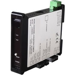
MLTE-FR | Ethernet & 4-20 mA Output | On/Off Duty Cycle | DIN Rail Transmitter
Duty cycle is a measure of ON or OFF period as a percentage of total period. Duty cycle is determined by averaging an integral number of periods over a gate time which is selectable from 10 ms to 199.99 s. The same signal is applied to Channels A and B. The transmitter divides the average pulse width t by the period P between pulses and expresses the ratio t/P in percent. A resolution of 1%, 0.1% or 0.01% is selectable. By selecting leading or falling pulse edges, ON or OFF duty cycle can be transmitted.
Pulse Width Modulation (PWM) is a transducer output format where the measured information is provided as duty cycle applied to a constant frequency, such as 120 Hz. As for duty cycle, the transmitter divides the average pulse width by the period between pulses over a gate time which is selectable from 10 ms to 199.99 s. It then scales this ratio mathematically to transmit this ratio in engineering units, such as relative humidity (RH).
The Micron duty cycle & pulse width modulation transmitter uses an Extended counter transmitter main board and the FR dual-channel signal conditioner board, which accepts signals from 12 mV to 250 Vac, inputs from proximity switches with an PNP or NPN output, TTL or CMOS logic, and contact closures. Jumper selections provide optimum operation for different sensor types and noise conditions. A built-in isolated 5, 10, or 24 Vdc excitation supply can power proximity switches and other sensors.
Standard features of Micron MLTE transmitters include:
- Ethernet I/O, isolated. Supported protocols are Modbus RTU and ASCII (tunneled via Modbus TCP) and Custom ASCII. The latter is simpler than the Modbus protocol and is recommended when all devices are Micron units. Note that RS232 or RS485 data I/O in lieu of Ethernet is provided by MLT Series transmitters.
- 4-20 mA, 0-20 mA or 0-10V analog transmitter output, isolated, jumper-selectable and user scalable. All selections provide 16-bit (0.0015%) resolution of output span and 0.02% output accuracy of a reading from -99,999 to +99,999 counts that is also transmitted digitally. Output isolation from signal and power grounds eliminates potential ground loop problems. The supply can drive 20 mA into a 500 ohm (or lower) load for 10V compliance, or 10V into a 5K ohm (or higher) load for 2 mA compliance.
- Dual solid state relays, isolated. Available for local alarm or control. Rated 120 mA at 130 Vac or 180 Vdc.
- Universal 85-264 Vac power. Low-voltage 10-48 Vdc or 12-32 Vac power is optional.
Discovery and configuration of the Ethernet Nodes is easily achieved with the Node Manager Software, and the discovered transmitters can then be programmed using the Instrument Setup Software. Both software's run on a PC under MS Windows and can be downloaded from this website at no charge.
![]() MLTE-FR On/Off Duty Cycle Transmitter | Support Library
MLTE-FR On/Off Duty Cycle Transmitter | Support Library
Data Sheet | User Manual