Your shopping cart is currently empty.
Micron Digital Panel Meter | Frequency | Rate & Period
Tech Note: For Detailed Information on the Meter and Option Modules click on the Tabs Below.
MM50 Series plug-in option modules offer the end-user exceptional accuracy, high speed (up to 60 readings / second), scalability, plus programmable features allow the MM50 Meters to be configured for applications from simple monitoring to computer interface and control. Setup can be from the front panel or by using powerful Setup & Calibration Software, which can be downloaded at no charge from our Software Download Page.
 Data logging software used with digital panel meters, counters and transmitters
Datalogging Software turns a PC connected to up to 31 Micron digital panel meters or digital counters into a powerful, low-cost datalogging system with virtual meter screen views plus arithmetic and totalizing capabilities.
Tech Note: For Detailed Information on the Option Modules click on the Tabs above.
View Summary Information on each module by Clicking on the icons below.
Micron MM50 Frequency, Rate & Period Meter
 12-32 Vac or 10-48 Vdc power input board(left)
85-264 Vac or 90-300 Vdc power input (right)
 4-Wire, 4-20mA Transmitter Wiring
 2-Wire, 4-20mA Transmitter Wiring
Both power supplies and their connectors (standard) are designed to UL/IEC/CSA safety standards. The two supplies also do double-duty by providing two connector inputs (A & B) and a digital ground for signals such as meter hold, reset, tare, etc. These signals do not affect power supply operation.
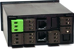
 Dual 8A Contact Relays
 Quad 8A Contact Relays
 Dual 120mA Solid State Relays
Quad 120mA Solid State Relays
Dual 120mA Solid State Relays
Quad 120mA Solid State Relays
 CE Mark
 RoHs Mark
 ETL Mark
 Made in the U.S.A.
 Form C (SPDT) dual contact relays
Relays can be connected to be normally open (OC) or normally closed ($0). Relay grounds are mutually isolated.
Form C (SPDT) dual contact relays
Relays can be connected to be normally open (OC) or normally closed ($0). Relay grounds are mutually isolated.
 Form A (SPST) quad contact relays
Relays are normally open (NO). Each pair of relays shares an isolated ground.
Form A (SPST) quad contact relays
Relays are normally open (NO). Each pair of relays shares an isolated ground.
 Form A (SPST) dual solid state relays
Relays are normally open (NO). Relay grounds are mutually isolated.
Form A (SPST) quad solid state relays
Relays are normally open (NO). Each pair of relays shares an isolated ground.
Form A (SPST) dual solid state relays
Relays are normally open (NO). Relay grounds are mutually isolated.
Form A (SPST) quad solid state relays
Relays are normally open (NO). Each pair of relays shares an isolated ground.
 Normal, Non-Latched Operation In this mode, the relay closes when the reading rises above the setpoint and opens when the reading falls below the setpoint. Relay ON/OFF control action is independently programmable for each of the two relays and can be reversed through a setup command.
 Latched Operation The relay stays actuated until reset externally. This mode can be used to shut down machinery or a process when an operating limit has been exceeded, or to maintain an alarm until acknowledged by an operator when the alarm condition has passed.
 Mixed Latched and Non-Latched Operation One of the relays can operate in a non-latched mode, for instance to turn off a heater when an operating temperature setpoint is reached. The other relay can operate as a latching fail-safe backup and turn off the entire process when a second, higher setpoint is reached, indicating a malfunction.
 Deviation Mode Operation A deviation limit (50 in this example) is set up around both sides of the setpoint. The relay closes (or opens) when the reading falls within the deviation band, and opens (or closes) when the reading falls outside of this band. This mode sets up a passband around the setpoint and is often used for component testing.
Wide Hysteresis Mode Operation In this example, a hysteresis limit of 600 is set below the setpoint. The relay closes when the reading reaches a lower limit (the setpoint less hysteresis) and opens when the reading reaches an upper limit (the setpoint). One application is automatic tank filling. A fill operation is automatically initiated when the tank level has reached a lower level and is terminated when the level has reached an upper level.
Deviation Mode Operation A deviation limit (50 in this example) is set up around both sides of the setpoint. The relay closes (or opens) when the reading falls within the deviation band, and opens (or closes) when the reading falls outside of this band. This mode sets up a passband around the setpoint and is often used for component testing.
Wide Hysteresis Mode Operation In this example, a hysteresis limit of 600 is set below the setpoint. The relay closes when the reading reaches a lower limit (the setpoint less hysteresis) and opens when the reading reaches an upper limit (the setpoint). One application is automatic tank filling. A fill operation is automatically initiated when the tank level has reached a lower level and is terminated when the level has reached an upper level.
 Narrow Hysteresis Mode Operation Hysteresis can be used to minimize the number of ON/OFF control cycles around a setpoint, thereby increasing the life of motors, relays, etc. A very narrow hysteresis band (such as 5 counts) can also be used to minimize relay chatter around a setpoint due to electrical noise on the signal, or due to signal feedback caused by load switching. The hysteresis limit should exceed the noise amplitude.
Specifications
Narrow Hysteresis Mode Operation Hysteresis can be used to minimize the number of ON/OFF control cycles around a setpoint, thereby increasing the life of motors, relays, etc. A very narrow hysteresis band (such as 5 counts) can also be used to minimize relay chatter around a setpoint due to electrical noise on the signal, or due to signal feedback caused by load switching. The hysteresis limit should exceed the noise amplitude.
Specifications
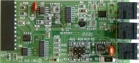
 16-Bit Analog Option Board
CE Mark
RoHs Mark
ETL Mark
Made in the U.S.A.
16-Bit Analog Option Board
CE Mark
RoHs Mark
ETL Mark
Made in the U.S.A.
 Serial Communication Option Boards
CE Mark
RoHs Mark
ETL Mark
Made in the U.S.A.
Serial Communication Option Boards
CE Mark
RoHs Mark
ETL Mark
Made in the U.S.A.
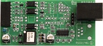
 Ethernet-to-RS485 converter board
Provides an RJ45 connector to an Ethernet LAN plus an RJ11 connector to an RS485 bus. Supports Ethernet communications with the host meter or counter plus an additional 30 meters or counters on the RS485 bus.
Ethernet-to-RS485 converter board
Provides an RJ45 connector to an Ethernet LAN plus an RJ11 connector to an RS485 bus. Supports Ethernet communications with the host meter or counter plus an additional 30 meters or counters on the RS485 bus.
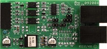
 RS232 interface board
Single RJ11 connector for point-to-point data communications to a PC RS232 COM port. Compatible with 4- or 6-wire data cables.
RS232 interface board
Single RJ11 connector for point-to-point data communications to a PC RS232 COM port. Compatible with 4- or 6-wire data cables.
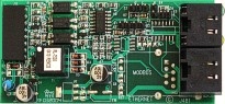
 RS485 interface boarddual RJ11 connectors
Dual RJ11 connectors allow daisy-chaining without a hub. Jumper selectable 2-wire (half duplex) or 4-wire (full duplex) connection. RJ11 connectors allow use of commercial 6-wire data cables.
RS485 interface boarddual RJ11 connectors
Dual RJ11 connectors allow daisy-chaining without a hub. Jumper selectable 2-wire (half duplex) or 4-wire (full duplex) connection. RJ11 connectors allow use of commercial 6-wire data cables.
 RS485 interface board, dual RJ45 connectors
Dual RJ45 connectors for daisy-chaining without a hub. Jumper selectable 2-wire (half duplex) or 4-wire (full duplex) connection. RJ45 connectors conform to the Modbus standard (but RJ11 connectors are more popular).
RS485 interface board, dual RJ45 connectors
Dual RJ45 connectors for daisy-chaining without a hub. Jumper selectable 2-wire (half duplex) or 4-wire (full duplex) connection. RJ45 connectors conform to the Modbus standard (but RJ11 connectors are more popular).
 USB 2.0 interface board
Single USB Type-B receptacle for USB 2.0 I/O. Allows plug-and-pay connection of meter to a PC with a USB port.
USB 2.0 interface board
Single USB Type-B receptacle for USB 2.0 I/O. Allows plug-and-pay connection of meter to a PC with a USB port.
 USB 2.0-to-RS485 converter board
Includes a USB Type-B receptacle for USB 2.0 I/O plus an RJ11 connector for RS485. Allows meter to communicate with a PC via USB while also serving as a USB-to-RS485 converter and server for up a 31-device RS485 network.
USB 2.0-to-RS485 converter board
Includes a USB Type-B receptacle for USB 2.0 I/O plus an RJ11 connector for RS485. Allows meter to communicate with a PC via USB while also serving as a USB-to-RS485 converter and server for up a 31-device RS485 network.
Micron MM50 Series Signal Conditioner Modules
Micron MM50 Digital Panel Meter

Micron MM50 Series Smart Programmable Digital Panel Meters
The MM50 Series is Micron's line of 1/8 DIN programmable 5-digit digital panel meters, 6-digit digital counters and timers, and 6-digit remote displays. Digit height is 14.2 mm (0.56").MM50 Series plug-in option modules offer the end-user exceptional accuracy, high speed (up to 60 readings / second), scalability, plus programmable features allow the MM50 Meters to be configured for applications from simple monitoring to computer interface and control. Setup can be from the front panel or by using powerful Setup & Calibration Software, which can be downloaded at no charge from our Software Download Page.
Data logging software used with digital panel meters, counters and transmittersDatalogging Software turns a PC connected to up to 31 Micron digital panel meters or digital counters into a powerful, low-cost datalogging system with virtual meter screen views plus arithmetic and totalizing capabilities.
Base Model Includes:
1/8 DIN Enclosure
Main Board with Green or Red Display
85-264 Volt AC Power Module
Signal Conditioner Module
Main Board with Green or Red Display
85-264 Volt AC Power Module
Signal Conditioner Module
View Summary Information on each module by Clicking on the icons below.
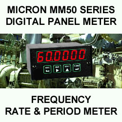
Micron MM50 Frequency, Rate & Period Meter
With dual, independently field-scalable channels
Features
- Two independently field-scalable channels A & B for frequency, rate or total
- Inputs from NPN or PNP proximity switches, contact closures, digital logic, magnetic pickups down to 12 mV, or AC inputs up to 250 Vac
- Frequencies from 0.005 Hz to 1 MHz
- Line frequency measurement to 60.0000 in a few line cycles
- Universal 85-264 Vac / 90-300 Vdc or 10-48 Vdc / 12-32 Vac power
- Transducer excitation output (isolated)
- Wide choice of options:
- 2 or 4 relays, mechanical or solid state (isolated)
- Analog output, 4-20 mA, 0-10V, or -10V to +10V (isolated)
- Serial data I/O: Ethernet, USB, RS485, RS232 (isolated)
- Custom curve linearization, rate from consecutive readings
| |
|
|
|
The Standard counter provides commonly used basic capabilities:
- The Micron dual-channel frequency, rate and period meter is a basic operating mode of the Micron counter with the FR signal conditioner board. It can display frequency from 0.005 Hz to 1 MHz, rate in engineering units, and period (inverse of frequency). The normal displayed value can range up to 999,999 counts. Above that level, the display will flash and go into four-digit XXXXEX scientific notation. Each channel (A or B) may be independently scaled for frequency, rate or period. The displayed channel is selected via a front panel push-button. Examples of applications are the accurate display of AC line frequency, RPM, speed from proximity switch inputs, and flow from turbine flow meter inputs.
- Fast, high resolution measurements. The Micron counter determines frequency by timing an integral number of periods over a specified gate time, and then taking the inverse of period. Rate is obtained by multiplying the input by a scale factor. The inverse period approach allows greater accuracy and faster update times than conventional meters which count signal pulses over a time interval. AC line frequency may be accurately measured to 50.0000 or 60.0000 Hz in a few line cycles. 1000 Hz signals may be measured to 0.01 Hz resolution at up to 25 readings per second. Fast response is ideal for alarm and control applications.
- For noise reduction, a count by 10 or 100 feature with rounding is selectable. Variations in the displayed reading can also be reduced by selecting a longer gate time. An adaptive digital filter is selectable to reduce variations due to noise while rapidly responding to actual changes in the signal.
An Extended counter version provides all capabilities of the Standard counter plus the following:
- Rate and total simultaneously. One channel can display total while the other displays rate. The selection for either channel is via a front panel push-button. This mode is ideal for flow applications when the same signal is applied to both channels.
- Custom curve linearization. Exceptionally accurate custom curve linearization allows linearization of the low end of turbine flow-meters. For setup, up to 180 data points can be input into a spreadsheet or text file by the user. The computer then calculates nonlinear segments, which are downloaded into the meter via RS232. The Extended version allows linearized rates to be totalized.
- Arithmetic functions. The Extended counter makes arithmetic functions available, namely A+B, A-B, AxB, A/B and A/B-1 (draw). For example, A+B allows two input flows to be summed for total flow, while A-B allows outflow to be subtracted from inflow for net flow. If transducers with a frequency output are used, AxB allows horsepower to be displayed based measured torque and RPM, or based on force and velocity. A/B can be used for the proper mixing of ingredients, while A/B-1 (draw) is used to compare rates for stretching or tensioning.
 The FR dual-channel signal conditioner accepts inputs from proximity switches with a PNP or NPN output, TTL or CMOS logic, magnetic pickups, contact closures, low-level outputs from turbine flow meters down to 12 mV, and high-level AC line inputs up to 250 Vac. A built-in isolated 5, 10, or 24 Vdc excitation supply can power proximity switches and other sensors, thus eliminating the need for an external power supply.
Designed for system use. Optional plug-in boards for communications and control include Ethernet and other serial communication boards, dual or quad relay boards, and single or dual isolated analog output boards. Microns may be powered from 85-264 Vac or optionally from 12-32 Vac or 10-48 Vdc. The display is available with red or green LEDs. The 1/8 DIN case meets NEMA 4X (IP65) specifications from the front when panel mounted. Any setup functions and front panel keys can be locked out for simplified usage and security. All power and signal connections are via UL / VDE / CSA rated screw clamp plugs.
Specifications
| Display | |
|---|---|
| Readout | 6 LED digits, 7-segment, 14.2 mm (.56"), red or green. |
| Display Range | -999999 to +999999, XXXXEX notation beyond 999999 |
| Zero Adjust | -999999 to +999999 |
| Span Adjust | 0 to 999999 |
| Indicators | Four LED lamps |
| Inputs | |
| Types | AC, pulses from NPN, PNP transistors, contact closures, magnetic pickups. |
| Signal Ground | Common ground for channels A & B |
| Channel A Freq. | 0.005 Hz to 1 MHz |
| Channel B Freq. | 0.005 Hz to 250 kHz |
| Minimum Signal | Nine ranges from (-12 to +12 mV) to (+1.25 to +2.1V). |
| Maximum Signal | 250 Vac |
| Noise Filter | 1 MHz, 30 kHz, 250 Hz (selectable) |
| Contact Debounce | 0, 3, 50 ms (selectable) |
| Update Rate | |
| Freq. Technique | Inverse period |
| Conversion Time | Gate time + 30 ms+ 0-2 signal periods |
| Gate Time | Selectable 10 ms to 199.99 s |
| Time Before Zero Out | Selectable 10 ms to 199.99 s |
| Accuracy | |
| Time Base | Crystal calibrated to ±2 ppm |
| Span tempco | ± 1 ppm/°C (typ) |
| Long-term Drift | ± 5 ppm/year |
|
Power Module
Power ModuleMicron MM50 Series Power Modules85-264 Vac / 90-300 Vdc, or 12-32 Vac / 10-48 Vdc Power Input Isolated 5, 10 & 24 Vdc Transducer Excitation Output12-32 Vac or 10-48 Vdc power input board(left)85-264 Vac or 90-300 Vdc power input (right) Key Features
DescriptionMicron's MM50 digital panel meters, digital counters and 6-digit remote display offer a choice of two high-frequency switching power supplies. These provide stable, isolated power for instrument operation plus excitation outputs at a substantially reduced weight and over a broader range of input voltages and power frequencies than conventional linear supplies.
Isolated Excitation OutputEach power supply provides three jumper-selectable, isolated excitation outputs: 5 Vdc at 100 mA, 10 Vdc at 120 mA, or 24 Vdc at 50 mA. These outputs can be used to power external sensors, transmitters and up to four 350 ohm load cells in parallel, thereby avoiding the need for an expensive external supply. When powering a load cell or potentiometer, a ratiometric operating mode can be selected, where the meter monitors the excitation supply and removes the effects of voltage variation. In addition to the isolated excitation output, regulated 5 Vdc at up to 50 mA is brought out and can be used to power external logic. Wiring of Excitation Output4-Wire, 4-20mA Transmitter Wiring2-Wire, 4-20mA Transmitter Wiring
Both power supplies and their connectors (standard) are designed to UL/IEC/CSA safety standards. The two supplies also do double-duty by providing two connector inputs (A & B) and a digital ground for signals such as meter hold, reset, tare, etc. These signals do not affect power supply operation.
|
||||||||||||||||||||||||||||||||||||||||||||||||||||||||||||||||||||||||||||||||||||||||||||||||||||||||||||||||||||||||||||||||||||||||||||||||||||||||
|---|---|---|---|---|---|---|---|---|---|---|---|---|---|---|---|---|---|---|---|---|---|---|---|---|---|---|---|---|---|---|---|---|---|---|---|---|---|---|---|---|---|---|---|---|---|---|---|---|---|---|---|---|---|---|---|---|---|---|---|---|---|---|---|---|---|---|---|---|---|---|---|---|---|---|---|---|---|---|---|---|---|---|---|---|---|---|---|---|---|---|---|---|---|---|---|---|---|---|---|---|---|---|---|---|---|---|---|---|---|---|---|---|---|---|---|---|---|---|---|---|---|---|---|---|---|---|---|---|---|---|---|---|---|---|---|---|---|---|---|---|---|---|---|---|---|---|---|---|---|---|---|---|
| Voltage, standard | 85-264 Vac or 90-300 Vdc | |||||||||||||||||||||||||||||||||||||||||||||||||||||||||||||||||||||||||||||||||||||||||||||||||||||||||||||||||||||||||||||||||||||||||||||||||||||||
| Voltage, optional | 12-32 Vac or 10-48 Vdc | |||||||||||||||||||||||||||||||||||||||||||||||||||||||||||||||||||||||||||||||||||||||||||||||||||||||||||||||||||||||||||||||||||||||||||||||||||||||
| Frequency | DC or 47-63 Hz | |||||||||||||||||||||||||||||||||||||||||||||||||||||||||||||||||||||||||||||||||||||||||||||||||||||||||||||||||||||||||||||||||||||||||||||||||||||||
| Power consumption (typical, base meter) | 1.2W @ 120 Vac, 1.5W @ 240 Vac, 1.3W @ 10 Vdc, 1.4W @ 20 Vdc, 1.55W @ 30 Vdc, 1.8W @ 40 Vdc, 2.15W @ 48 Vdc | |||||||||||||||||||||||||||||||||||||||||||||||||||||||||||||||||||||||||||||||||||||||||||||||||||||||||||||||||||||||||||||||||||||||||||||||||||||||
| Power Isolation | 250V rms working, 2.3 kV rms per 1 min test | |||||||||||||||||||||||||||||||||||||||||||||||||||||||||||||||||||||||||||||||||||||||||||||||||||||||||||||||||||||||||||||||||||||||||||||||||||||||
| Excitation Output (standard) | ||||||||||||||||||||||||||||||||||||||||||||||||||||||||||||||||||||||||||||||||||||||||||||||||||||||||||||||||||||||||||||||||||||||||||||||||||||||||
| 5 Vdc | 5 Vdc ± 5%, 100 mA | |||||||||||||||||||||||||||||||||||||||||||||||||||||||||||||||||||||||||||||||||||||||||||||||||||||||||||||||||||||||||||||||||||||||||||||||||||||||
| 10 Vdc | 10 Vdc ± 5%, 120 mA | |||||||||||||||||||||||||||||||||||||||||||||||||||||||||||||||||||||||||||||||||||||||||||||||||||||||||||||||||||||||||||||||||||||||||||||||||||||||
| 24 Vdc | 24 Vdc ± 5%, 50 mA | |||||||||||||||||||||||||||||||||||||||||||||||||||||||||||||||||||||||||||||||||||||||||||||||||||||||||||||||||||||||||||||||||||||||||||||||||||||||
| Output Isolation | 50 Vdc to meter ground | |||||||||||||||||||||||||||||||||||||||||||||||||||||||||||||||||||||||||||||||||||||||||||||||||||||||||||||||||||||||||||||||||||||||||||||||||||||||
|
Analog Output Module (Optional)
Analog OutputMicron MM50 Meter 16-Bit Analog Output Option Module16-Bit Analog Option BoardKey Features
CE MarkETL MarkMade in the U.S.A.Description
A 16-bit analog output option board can turn a Micron 1/8 DIN digital panel meter, counter, timer or remote display into a superb, isolated, linearized transmitter or signal conditioner with exceptional accuracy and high-speed response. The analog output for thermocouples, RTDs and custom curves is linearized to the displayed reading. The analog output can be selected as 4-20 mA, 0-20 mA, unipolar 0-10V, or bipolar -10V to +10V with a 20V span and 0V at mid-range. If a voltage output is selected, output pins 1 and 2 may be reversed to provide reversed polarity. A 16-bit D-to-A converter provides 0.0015% full-scale resolution and ±0.02% full-scale accuracy. The update rate for meters is a fast 60/sec for 60 Hz power or 50/sec at 50 Hz power. The analog output can track the unfiltered signal for fastest response, or a digitally filtered signal for best noise rejection. Isolation from power and signal is provided by a separate power supply in the meter. This supply can drive 20 mA of current into loads up to 600 ohms for 12V compliance. Isolation to signal ground and power ground eliminates problems caused by ground loops. Scaling of the analog output can be via the meter's front panel pushbuttons or a serial digital interface using Instrument Setup software. The displayed readings to produce the low and high analog outputs can be set to any value from -99999 to +99999 for DPMs or from -999999 to +999999 for counters and timers. Depending on your selected output range, simply set the meter reading for low analog output (4 mA, 0 mA, 0V or -10V) and for high analog output (20 mA or 10V).
Micron DIN rail transmitters come standard with a 4-20 mA, 0-20 mA, 0-10V, or bipolar -10 to +10V analog output with 16-bit resolution. Specifications
|
||||||||||||||||||||||||||||||||||||||||||||||||||||||||||||||||||||||||||||||||||||||||||||||||||||||||||||||||||||||||||||||||||||||||||||||||||||||||
| Output levels | 4-20 mA, 0-20 mA, 0-10V, -10 to +10V (jumper selectable) | |||||||||||||||||||||||||||||||||||||||||||||||||||||||||||||||||||||||||||||||||||||||||||||||||||||||||||||||||||||||||||||||||||||||||||||||||||||||
| Current compliance | 2 mA at 10V ( > 5 kΩ load) | |||||||||||||||||||||||||||||||||||||||||||||||||||||||||||||||||||||||||||||||||||||||||||||||||||||||||||||||||||||||||||||||||||||||||||||||||||||||
| Voltage compliance | 12V at 20 mA (< 60Ω load) | |||||||||||||||||||||||||||||||||||||||||||||||||||||||||||||||||||||||||||||||||||||||||||||||||||||||||||||||||||||||||||||||||||||||||||||||||||||||
| Scaling | Zero and full scale adjustable from -99999 to +99999 | |||||||||||||||||||||||||||||||||||||||||||||||||||||||||||||||||||||||||||||||||||||||||||||||||||||||||||||||||||||||||||||||||||||||||||||||||||||||
| Resolution | 16 bits (0.0015% of full scale) | |||||||||||||||||||||||||||||||||||||||||||||||||||||||||||||||||||||||||||||||||||||||||||||||||||||||||||||||||||||||||||||||||||||||||||||||||||||||
| Isolation | 250V rms working, 2.3 kV rms per 1 min test | |||||||||||||||||||||||||||||||||||||||||||||||||||||||||||||||||||||||||||||||||||||||||||||||||||||||||||||||||||||||||||||||||||||||||||||||||||||||
|
Relay Outputs (optional)
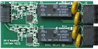
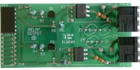
Relay ModuleMicron MM50 Meter Dual or Quad Relay Option ModulesDual 8A Contact RelaysQuad 8A Contact RelaysDual 120mA Solid State RelaysQuad 120mA Solid State RelaysCE MarkETL MarkMade in the U.S.A.DescriptionStandard Features
- Two contact relays
- Two solid state relays
- Four contact relays
- Four solid state relays
- Output above or below setpoint
- Latching or non-latching
- Band deviation or hysteresis around each setpoint
Electrocontact or Solid State RelaysFour optional plug-in setpoint controller boards are available to add control and alarm capability to 1/8 DIN Micron DPMs, counters, timers and remote displays:
The contact relays are rated for 8A at 250 Vac or 24 Vdc and are recommended for high currents. The dual contact relays are mutually isolated Form C relays and can be wired to be normally open (NO) or normally closed ($0) when not energized. The quad contact relays are normally open (NO) Form A relays and share a common isolated ground in pairs. The solid state relays are rated for 120 mA at 250 Vac or 24 Vdc and are recommended for low currents and frequent switching. They are Form A relays, which are normally open (NO) when not energized. As for the contact relays, the dual solid state relays are mutually isolated, and the quad solid state relays share a common isolated ground in pairs. Operating Modes
Relay SetupSetpoint values and operating modes can be entered via front panel pushbuttons or by computer via the serial interface. Security lockout modes of the front panel pushbuttons can be set to allow operators to view and change setpoint values, view but not changes setpoint values, or not view nor change setpoint values. The Micron Weight Meter and Batch Controller offer relay control modes beyond those of normal meter or counter operation. Electrical ConnectionsForm C (SPDT) dual contact relays
Relays can be connected to be normally open (OC) or normally closed ($0). Relay grounds are mutually isolated.Form A (SPST) quad contact relays
Relays are normally open (NO). Each pair of relays shares an isolated ground.Form A (SPST) dual solid state relays
Relays are normally open (NO). Relay grounds are mutually isolated. Form A (SPST) quad solid state relays
Relays are normally open (NO). Each pair of relays shares an isolated ground.Setpoint Operating ModesNormal, Non-Latched Operation In this mode, the relay closes when the reading rises above the setpoint and opens when the reading falls below the setpoint. Relay ON/OFF control action is independently programmable for each of the two relays and can be reversed through a setup command.Latched Operation The relay stays actuated until reset externally. This mode can be used to shut down machinery or a process when an operating limit has been exceeded, or to maintain an alarm until acknowledged by an operator when the alarm condition has passed.Mixed Latched and Non-Latched Operation One of the relays can operate in a non-latched mode, for instance to turn off a heater when an operating temperature setpoint is reached. The other relay can operate as a latching fail-safe backup and turn off the entire process when a second, higher setpoint is reached, indicating a malfunction.Deviation Mode Operation A deviation limit (50 in this example) is set up around both sides of the setpoint. The relay closes (or opens) when the reading falls within the deviation band, and opens (or closes) when the reading falls outside of this band. This mode sets up a passband around the setpoint and is often used for component testing. Wide Hysteresis Mode Operation In this example, a hysteresis limit of 600 is set below the setpoint. The relay closes when the reading reaches a lower limit (the setpoint less hysteresis) and opens when the reading reaches an upper limit (the setpoint). One application is automatic tank filling. A fill operation is automatically initiated when the tank level has reached a lower level and is terminated when the level has reached an upper level.Narrow Hysteresis Mode Operation Hysteresis can be used to minimize the number of ON/OFF control cycles around a setpoint, thereby increasing the life of motors, relays, etc. A very narrow hysteresis band (such as 5 counts) can also be used to minimize relay chatter around a setpoint due to electrical noise on the signal, or due to signal feedback caused by load switching. The hysteresis limit should exceed the noise amplitude.
|
||||||||||||||||||||||||||||||||||||||||||||||||||||||||||||||||||||||||||||||||||||||||||||||||||||||||||||||||||||||||||||||||||||||||||||||||||||||||
| Relay types | 2 Form C contact relays or 4 Form A contact relays (NO) 2 or 4 Form A, AC/DC solid state relays (NO) | |||||||||||||||||||||||||||||||||||||||||||||||||||||||||||||||||||||||||||||||||||||||||||||||||||||||||||||||||||||||||||||||||||||||||||||||||||||||
| Current tatings | 8A at 250 Vac or 24 Vdc for contact relays 120 mA at 140 Vac or 180 Vdc for solid state relays | |||||||||||||||||||||||||||||||||||||||||||||||||||||||||||||||||||||||||||||||||||||||||||||||||||||||||||||||||||||||||||||||||||||||||||||||||||||||
| Output common | Isolated commons for dual relays or each pair of quad relays | |||||||||||||||||||||||||||||||||||||||||||||||||||||||||||||||||||||||||||||||||||||||||||||||||||||||||||||||||||||||||||||||||||||||||||||||||||||||
| Isolation | 250V rms working, 2.3 kV rms per 1 min tes | |||||||||||||||||||||||||||||||||||||||||||||||||||||||||||||||||||||||||||||||||||||||||||||||||||||||||||||||||||||||||||||||||||||||||||||||||||||||
|
Serial Communication I/O (optional)
Serial I/O ModuleMicron MM50 Meter Serial Communication Option ModulesSerial Communication Option BoardsKey Features
CE MarkETL MarkMade in the U.S.A.Description
If the primary objective is to program a meter directly from a PC using Instrument Setup Software, an RS232 or USB interface board is recommended, depending on the available PC port. Once the meter has been programmed, the interface board can be removed if no longer needed. If the objective is to connect a network of meters to a PC, our USB 2.0-to-RS485 converter board can be used. That board can be connected to a PC via a USB port, and also act as the server for up to 31 meters on an RS485 bus via an RJ11 connector. The remote meters must be equipped with Micron RS485 interface board. That board features dual RJ11 connectors for RS485 daisy-chaining using commercial 6-wire RJ11 data cables, with no need for a hub. If the objective is to connect meters to an existing Modbus RS485 bus, either of two RS485 interface board can be selected. Our RS485 Modbus interface board uses RJ45 connectors as recommended by the Modbus standard, while our RS485 interface board uses RJ11 connectors, which are also used for Modbus. Both boards are fully compatible with the Modbus RTU and Modbus ASCII protocols, as are all other Micron serial interface boards. Both RS485 boards provide dual connectors (RJ485 or RJ11) for RS485 daisy-chaining using commercial 6-wire data cables with the appropriate connector (RJ485 or RJ11), with no need for a hub. If the objective is to connect a meter to an Ethernet LAN, our Ethernet interface board allows a meter to be connected to an available router port using a standard Ethernet cable. Our Node Manager software makes node discovery and setup exceptionally simple. If the objective is to connect a network of meters to an Ethernet LAN, our new Ethernet-to-RS485 converter board should be selected. That board can be connected to an Ethernet LAN utilizing a single Ethernet cable and also act as the server for up to 31 meters on an RS485 bus via an RJ11 connector. The remote meters must be equipped with Micron RS485 interface board. The Ethernet-to-RS485 converter board features dual RJ11 connectors for RS485 daisy-chaining using commercial 6-wire RJ11 data cables, with no need for a hub. Our new Node Manager software makes meter discovery and setup exceptionally simple. Three serial protocols are user-selectable: Modbus RTU, Modbus ASCII, and Micron ASCII. For more information, please see our Modbus Protocol Serial Communications Manual and our Serial Communications Manual.
Quick Selection Guide
SpecificationsElectrical Specifications
Communication Option Module OverviewEthernet-to-RS485 converter board
Provides an RJ45 connector to an Ethernet LAN plus an RJ11 connector to an RS485 bus. Supports Ethernet communications with the host meter or counter plus an additional 30 meters or counters on the RS485 bus.
RS232 interface board
Single RJ11 connector for point-to-point data communications to a PC RS232 COM port. Compatible with 4- or 6-wire data cables.
RS485 interface boarddual RJ11 connectors
Dual RJ11 connectors allow daisy-chaining without a hub. Jumper selectable 2-wire (half duplex) or 4-wire (full duplex) connection. RJ11 connectors allow use of commercial 6-wire data cables. RS485 interface board, dual RJ45 connectors
Dual RJ45 connectors for daisy-chaining without a hub. Jumper selectable 2-wire (half duplex) or 4-wire (full duplex) connection. RJ45 connectors conform to the Modbus standard (but RJ11 connectors are more popular).
USB 2.0 interface board
Single USB Type-B receptacle for USB 2.0 I/O. Allows plug-and-pay connection of meter to a PC with a USB port.
USB 2.0-to-RS485 converter board
Includes a USB Type-B receptacle for USB 2.0 I/O plus an RJ11 connector for RS485. Allows meter to communicate with a PC via USB while also serving as a USB-to-RS485 converter and server for up a 31-device RS485 network. |
||||||||||||||||||||||||||||||||||||||||||||||||||||||||||||||||||||||||||||||||||||||||||||||||||||||||||||||||||||||||||||||||||||||||||||||||||||||||
| Board selections | RS232, RS485 (dual RJ11 or RJ45 connectors), USB, Ethernet, USB-to-RS485 converter, Ethernet-to-RS485 converter | |||||||||||||||||||||||||||||||||||||||||||||||||||||||||||||||||||||||||||||||||||||||||||||||||||||||||||||||||||||||||||||||||||||||||||||||||||||||
| Protocols | Modbus RTU, Modbus ASCII, Modbus TCP (Ethernet), Custom ASCII | |||||||||||||||||||||||||||||||||||||||||||||||||||||||||||||||||||||||||||||||||||||||||||||||||||||||||||||||||||||||||||||||||||||||||||||||||||||||
| Data rates | 300 to 19200 baud | |||||||||||||||||||||||||||||||||||||||||||||||||||||||||||||||||||||||||||||||||||||||||||||||||||||||||||||||||||||||||||||||||||||||||||||||||||||||
| Digital addresses | 247 (Modbus), 31 (Custom ASCII), | |||||||||||||||||||||||||||||||||||||||||||||||||||||||||||||||||||||||||||||||||||||||||||||||||||||||||||||||||||||||||||||||||||||||||||||||||||||||
| Isolation | 250V rms working, 2.3 kV rms per 1 min test | |||||||||||||||||||||||||||||||||||||||||||||||||||||||||||||||||||||||||||||||||||||||||||||||||||||||||||||||||||||||||||||||||||||||||||||||||||||||
| Signal Connections | ||||||||||||||||||||||||||||||||||||||||||||||||||||||||||||||||||||||||||||||||||||||||||||||||||||||||||||||||||||||||||||||||||||||||||||||||||||||||
 |
||||||||||||||||||||||||||||||||||||||||||||||||||||||||||||||||||||||||||||||||||||||||||||||||||||||||||||||||||||||||||||||||||||||||||||||||||||||||
| Environmental | ||||||||||||||||||||||||||||||||||||||||||||||||||||||||||||||||||||||||||||||||||||||||||||||||||||||||||||||||||||||||||||||||||||||||||||||||||||||||
| Operating temperature | 0°C to 55°C | |||||||||||||||||||||||||||||||||||||||||||||||||||||||||||||||||||||||||||||||||||||||||||||||||||||||||||||||||||||||||||||||||||||||||||||||||||||||
| Storage temperature. | -40°C to 85°C | |||||||||||||||||||||||||||||||||||||||||||||||||||||||||||||||||||||||||||||||||||||||||||||||||||||||||||||||||||||||||||||||||||||||||||||||||||||||
| Relative humidity | 95% at 40°C, non-condensing | |||||||||||||||||||||||||||||||||||||||||||||||||||||||||||||||||||||||||||||||||||||||||||||||||||||||||||||||||||||||||||||||||||||||||||||||||||||||
| Protection | NEMA-4X (IP-65) when panel mounted | |||||||||||||||||||||||||||||||||||||||||||||||||||||||||||||||||||||||||||||||||||||||||||||||||||||||||||||||||||||||||||||||||||||||||||||||||||||||
Applications
|
AC Line Frequency |
|
|---|---|
 |
The Micron will accept line voltages up to 250 Vac and display line frequency to 6-digit accuracy (50.0000 or 60.0000) in a few line cycles. Fast low frequency response is achieved by timing the period and taking its inverse. |
| RPM and Speed | |
 |
The Micron can sense the low-level signals from magnetic pickups or the NPN or PNP transistor output of active sensors. These can be powered directly by the meter. Display in RPM or units of speed is achieved by mathematically scaling the meter. |
| Flow Rate and Simultaneous Total | |
 |
The Micron is compatible with all flow meters which generate pulses at a frequency proportional to flow rate. The Extended version can display scaled rate or total for the same input at the push of a button, and alarm from both the rate and total. The Extended version can also linearize flow transducers so as to extend their dynamic range. |
| Arithmetic Combinations of Two Channels | |
 |
The Extended Micron offers A+B, A-B and A/B arithmetic functions. A+B allows two input flows to be summed for total flow, while A-B allows outflow to be subtracted from inflow for net flow. Flow ratios aid in the proper mixing of ingredients |
| Custom Curve Linearization | |
 |
The Extended Micron can linearize the output turbine flow meters, which tend to be nonlinear on the low end. Linearizing improves the dynamic range and accuracy of turbine flow meters. |
| System-level Capabilities | |
| The Micron dual channel rate meter can independently scale, display and alarm two pulse input channels. All signal or alarm data can further be transmitted via RS232 or RS485, including peak readings and arithmetic combinations of the two rates. The displayed rates can also be transmitted as an isolated 4-20 mA or 0-10V analog output. |  |
Micron MM50 Series Power Modules
85-264 Vac / 90-300 Vdc, or 12-32 Vac / 10-48 Vdc Power Input Isolated 5, 10 & 24 Vdc Transducer Excitation Output12-32 Vac or 10-48 Vdc power input board(left)85-264 Vac or 90-300 Vdc power input (right)
Key Features
- Lightweight, high-frequency switching power supply design.
- 85-264 Vac or 90-300 Vdc power version
- 12-32 Vac or 10-48 Vdc power version
- Isolated 5, 10 or 24 Vdc transducer excitation output
- UL Recognized on-board fuse
- Three selectable isolated excitation outputs
- Certified to EN 61010-1 (CE mark) and RoHS
- ETL certified to UL 61010-1 and CSA C22.2#61010-1
Description
Micron's MM50 digital panel meters, digital counters and 6-digit remote display offer a choice of two high-frequency switching power supplies. These provide stable, isolated power for instrument operation plus excitation outputs at a substantially reduced weight and over a broader range of input voltages and power frequencies than conventional linear supplies.- High voltage AC or DC power. The standard Micron supply accepts power from 85-264 Vac, 47-63 Hz. This allows the same meter to operate worldwide without modification. The supply also accepts 90 to 300 Vdc (high voltage DC operation not ETL approved).
- Low voltage AC or DC power. An optional low voltage supply operates from 10 to 48 Vdc or 12 to 30 Vac, 47-63 Hz. This supply allows the Micron to be powered from batteries or from 28 Vac, 400 Hz aircraft power (400 Hz operation not ETL approved).
Isolated Excitation Output
Each power supply provides three jumper-selectable, isolated excitation outputs: 5 Vdc at 100 mA, 10 Vdc at 120 mA, or 24 Vdc at 50 mA. These outputs can be used to power external sensors, transmitters and up to four 350 ohm load cells in parallel, thereby avoiding the need for an expensive external supply. When powering a load cell or potentiometer, a ratiometric operating mode can be selected, where the meter monitors the excitation supply and removes the effects of voltage variation.
In addition to the isolated excitation output, regulated 5 Vdc at up to 50 mA is brought out and can be used to power external logic.
Wiring of Excitation Output
4-Wire, 4-20mA Transmitter Wiring2-Wire, 4-20mA Transmitter Wiring- With four-wire transmitters, two wires are used to apply 10 or 24 Vdc, and two separate wires are used to sense the transmitter's 4-20 mA output.
- With two-wire transmitters, the same two wires are used to power the transmitter and carry the 4-20 mA output, which is made to flow across an internal 10 ohm resistor between pins 3 and 4.
Both power supplies and their connectors (standard) are designed to UL/IEC/CSA safety standards. The two supplies also do double-duty by providing two connector inputs (A & B) and a digital ground for signals such as meter hold, reset, tare, etc. These signals do not affect power supply operation.
| OPERATING POWER | |
|---|---|
| Module PS1 Module PS2 Frequency Power Consumption |
85-264 Vac or 90-300 Vdc 12-32 Vac or 10-48 Vdc DC and 47-63 Hz 5.3 W max |
| PROTECTION | |
| Module PS1 Module PS2 |
Module PS2 On-board fuse rated 0.5A, 277 Vac, UL Recognized On-board fuse rated 2.5A at 250 Vac or 63 Vdc, UL Recognized |
| EXCITATION POWER SUPPLY | |
|
Selectable Outputs |
5 Vdc ± 5%, 100 mA 10 Vdc ± 5%, 120 mA 24 Vdc ± 5%, 50 mA |
| Ripple Isolation to Power Gound Isolation to Meter Ground |
50 mVp-p max 250V rms working, 2.3 kV rms per 1 min test 50 Vp |
| PIN ASSIGNMENT (POWER & DIGITAL CONTROLS) | |
 |
Micron MM50 Meter Dual or Quad Relay Option Modules
Dual 8A Contact RelaysQuad 8A Contact RelaysDual 120mA Solid State RelaysQuad 120mA Solid State RelaysCE MarkETL MarkMade in the U.S.A.Description
Standard Features
- Fits all 1/8 DIN Micron DPMs, counters, timers & remote displays
- Choice of four relay output boards :
- Two contact relays
- Two solid state relays
- Four contact relays
- Four solid state relays
- Contact relays rated 8A at 250 Vac or 24 Vdc
- Solid state relays rated 120 mA at 140 Vac or 180 Vdc
- Outputs can be based on filtered or unfiltered signal input
- Responds in one reading or after programmable delay
- Selectable operating modes:
- Output above or below setpoint
- Latching or non-latching
- Band deviation or hysteresis around each setpoint
- Setpoint setup via front panel pushbuttons or a PC
- Security lockout of front panel setpoint controls
- Certified to EN 61010-1 (CE mark) and RoHS
Electrocontact or Solid State Relays
Four optional plug-in setpoint controller boards are available to add control and alarm capability to 1/8 DIN Micron DPMs, counters, timers and remote displays:
- Two contact relays
- Two solid state relays
- Four contact relays
- Four solid state relays
The contact relays are rated for 8A at 250 Vac or 24 Vdc and are recommended for high currents. The dual contact relays are mutually isolated Form C relays and can be wired to be normally open (NO) or normally closed ($0) when not energized. The quad contact relays are normally open (NO) Form A relays and share a common isolated ground in pairs.
The solid state relays are rated for 120 mA at 250 Vac or 24 Vdc and are recommended for low currents and frequent switching. They are Form A relays, which are normally open (NO) when not energized. As for the contact relays, the dual solid state relays are mutually isolated, and the quad solid state relays share a common isolated ground in pairs.
Operating Modes
- Operation above or below setpoint. Each relay may be individually programmed to be energized above or below a setpoint, or may be disabled.
- Latching or non-latching. Each relay may be individually programmed to operate in a latching or non-latching mode. In the latching mode, when an alarm or shutdown condition is reached, the output remains in the alarm condition until it is reset by front panel pushbuttons, via the serial interface, or via the rear connector. In the non-latching mode, the output is automatically reset when the alarm condition no longer exists.
- Band deviation mode. Each relay may be set to operate in a band deviation mode, where an alarm is generated whenever the reading is a specified number of counts above or below the setpoint. In particular, band deviation is ideal to flag an out-of-tolerance condition.
- Hysteresis mode. Each relay may be set to operate in a hysteresis mode, where turn-on occurs at a specified amount above the setpoint and turn-off occurs at the same amount below the setpoint.
- Filtered or unfiltered input. Relay action may be derived from either the filtered or unfiltered DPM input signals. Using the unfiltered signal improves response time, which is typically 17 ms for a DPM with the solid state relay board. Fast response time is one of the major strengths of Micron DPMs, which can digitize analog data as often as 60 times per second. Using the filtered input reduces the chance of alarm triggering due to noise.
- Provisions for signal noise. A programmable time delay and reduction of relay chatter can be achieved in the DPM by selecting 1 to 128 readings in binary steps (17 ms to 2.1 s) prior to updating the output. Snubber circuitry is part of the contact relay board to prolong contact life. The relay response time of counters is controlled by a selectable gate time from 10 ms to 199.99 s.
Relay Setup
Setpoint values and operating modes can be entered via front panel pushbuttons or by computer via the serial interface. Security lockout modes of the front panel pushbuttons can be set to allow operators to view and change setpoint values, view but not changes setpoint values, or not view nor change setpoint values. The Micron Weight Meter and Batch Controller offer relay control modes beyond those of normal meter or counter operation.
Electrical Connections
Form C (SPDT) dual contact relays
Relays can be connected to be normally open (OC) or normally closed ($0). Relay grounds are mutually isolated.Form A (SPST) quad contact relays
Relays are normally open (NO). Each pair of relays shares an isolated ground.Form A (SPST) dual solid state relays
Relays are normally open (NO). Relay grounds are mutually isolated. Form A (SPST) quad solid state relays
Relays are normally open (NO). Each pair of relays shares an isolated ground.Setpoint Operating Modes
Normal, Non-Latched Operation In this mode, the relay closes when the reading rises above the setpoint and opens when the reading falls below the setpoint. Relay ON/OFF control action is independently programmable for each of the two relays and can be reversed through a setup command.Latched Operation The relay stays actuated until reset externally. This mode can be used to shut down machinery or a process when an operating limit has been exceeded, or to maintain an alarm until acknowledged by an operator when the alarm condition has passed.Mixed Latched and Non-Latched Operation One of the relays can operate in a non-latched mode, for instance to turn off a heater when an operating temperature setpoint is reached. The other relay can operate as a latching fail-safe backup and turn off the entire process when a second, higher setpoint is reached, indicating a malfunction.Deviation Mode Operation A deviation limit (50 in this example) is set up around both sides of the setpoint. The relay closes (or opens) when the reading falls within the deviation band, and opens (or closes) when the reading falls outside of this band. This mode sets up a passband around the setpoint and is often used for component testing. Wide Hysteresis Mode Operation In this example, a hysteresis limit of 600 is set below the setpoint. The relay closes when the reading reaches a lower limit (the setpoint less hysteresis) and opens when the reading reaches an upper limit (the setpoint). One application is automatic tank filling. A fill operation is automatically initiated when the tank level has reached a lower level and is terminated when the level has reached an upper level.Narrow Hysteresis Mode Operation Hysteresis can be used to minimize the number of ON/OFF control cycles around a setpoint, thereby increasing the life of motors, relays, etc. A very narrow hysteresis band (such as 5 counts) can also be used to minimize relay chatter around a setpoint due to electrical noise on the signal, or due to signal feedback caused by load switching. The hysteresis limit should exceed the noise amplitude.
| Operation | |
|---|---|
| Power | Provided by meter |
| Setup | Front panel pushbuttons or via PC using RS232, RS485 or USB |
| Input Filtering | Setpoint compared to either filtered or unfiltered signal. |
| Time Delay | Unfiltered, or programmable delay from 1 to 128 readings |
| Relay Operating Modes | 1) Activate above or below setpoint |
| 2) Latching or non-latching | |
| 3) Hysteresis or band deviation mode around each setpoint | |
| 4) Relays disabled | |
| Enable/Lockout Modes | 1) Display and change setpoint via front panel pushbuttons. |
| 2) Display setpoints via alarm pushbutton, but do not allow changes. | |
| 3) Disable pushbutton action for setpoints. | |
| Alarm Status Indication | |
| Type | Two or four red LED indicators |
| Lamp Lit | When relay is energized |
| Contact Relay Versions | |
| Form, Dual Relays | Form C, single-pole, double-throw (SPDT) |
| Form, Quad Relays | Form A, single-pole, single-throw (SPST), normally open (NO) |
| Current Rating | 8A at 250 Vac or 24 Vdc |
| Safety Rating | 250V rms working, 2.3 kV rms per 1 min test |
| Relay Grounds | Grounds of dual relays are mutually isolated |
| Grounds of quad relays are isolated in pairs | |
| Operate Time | 7 ms (typical) from end of conversion |
| Release Time | 5 ms (typical) from end of conversion |
| Solid State Relay Versions | |
| Form of Relays | Form A, single-pole, single-throw (SPST), normally open (NO) |
| Current Rating | 120 mA at 140 Vac or 180 Vdc |
| ON series resistance | 18 ohms typical, 25 ohms max |
| Isolation Type | Optical |
| Safety Rating | 250V rms working, 2.3 kV rms per 1 min test |
| Operate & Release Time | 1 ms (typical) from end of conversion |
| Environmental | |
| Operating temperature | 0°C to 60°C |
| Storage temperature. | -40°C to 85°C |
| Relative humidity | 95% at 40°C, non-condensing |
Micron MM50 Meter 16-Bit Analog Output Option Module
16-Bit Analog Option BoardKey Features
- 16-bit resolution (1 part in 65,536 or 0.0015% of full scale)
- 4-20 mA, 0-20 mA, 0-10V, or bipolar -10 to +10V analog output
- Analog output linearized to reading
- Analog output isolated to 250 Vac
- ±0.02% full scale accuracy
- Scale and offset via meter front panel, RS232, RS485 or USB
- Certified to EN 61010-1 (CE mark) and RoHS
- Output derived from filtered or unfiltered signal input
- 12V compliance at 20 mA
CE MarkETL MarkMade in the U.S.A.Description
A 16-bit analog output option board can turn a Micron 1/8 DIN digital panel meter, counter, timer or remote display into a superb, isolated, linearized transmitter or signal conditioner with exceptional accuracy and high-speed response. The analog output for thermocouples, RTDs and custom curves is linearized to the displayed reading.
The analog output can be selected as 4-20 mA, 0-20 mA, unipolar 0-10V, or bipolar -10V to +10V with a 20V span and 0V at mid-range. If a voltage output is selected, output pins 1 and 2 may be reversed to provide reversed polarity.
A 16-bit D-to-A converter provides 0.0015% full-scale resolution and ±0.02% full-scale accuracy. The update rate for meters is a fast 60/sec for 60 Hz power or 50/sec at 50 Hz power. The analog output can track the unfiltered signal for fastest response, or a digitally filtered signal for best noise rejection.
Isolation from power and signal is provided by a separate power supply in the meter. This supply can drive 20 mA of current into loads up to 600 ohms for 12V compliance. Isolation to signal ground and power ground eliminates problems caused by ground loops.
Scaling of the analog output can be via the meter's front panel pushbuttons or a serial digital interface using Instrument Setup software. The displayed readings to produce the low and high analog outputs can be set to any value from -99999 to +99999 for DPMs or from -999999 to +999999 for counters and timers. Depending on your selected output range, simply set the meter reading for low analog output (4 mA, 0 mA, 0V or -10V) and for high analog output (20 mA or 10V).
 The bipolar -10V to +10V analog output can provide a negative signal for a negative deviation from a setpoint, and a positive signal for a positive deviation. It can also be used for proportional control around a setpoint. For example, if proportional control is desired around 170°C with a ±10°C span, set the -10V output to 160°C and the +10V output to 180°C. The control signal will be 0V at 170°C.
Micron DIN rail transmitters come standard with a 4-20 mA, 0-20 mA, 0-10V, or bipolar -10 to +10V analog output with 16-bit resolution.
Specifications
| Electrical | |||
|---|---|---|---|
| Power source | Provided by meter | ||
| Signal source | Filtered or unfiltered digitized signal | ||
| Output linearization | Linearized to reading | ||
| Output Levels (selectable) | 4-20 mA, 0-20 mA, 0-10V, -10 to 10V | ||
| Compliance at 20 mA | 12V ( 600 Ω max load ) | ||
| Compliance at 10 V | 2 mA ( 5 kΩ min load) | ||
| Isolation | 250V rms working, 2.3 kV rms per 1 min test | ||
| Output resolution | 16 bits (0.0015% of full scale) | ||
| Output nonlinearity | < 0.01% of full scale | ||
| Accuracy | < 0.02% of full scale | ||
| Output update rate, DPMs | 50 or 60/sec (output may be digitally filtered) | ||
| Output update rate, counter rate meter | Gate time + 30 ms + 0-2 periods | ||
| Scaling | |||
| Zero output & full-scale output, DPMs | -99,999 to +99,999 counts | ||
| Zero output & full-scale output, counters | -999,999 to +999,999 counts | ||
| Minimum span | 150 counts | ||
| J4 Pin Assignments | |||
| Unipolar Connections | Bipolar Connections | ||
| 4-20 mA or 0-20 mA output 1 |  |
Reference or Return 1 | |
| 0-10V output 2 | -10V to +10V Output 2 | ||
| Isolated ground 3 | N/C 3 | ||
Micron MM50 Meter Serial Communication Option Modules
Serial Communication Option BoardsKey Features
- Communication boards available for RS232, RS485, USB, Ethernet
- Usable in all 1/8 DIN size Laureate DPMs, counters, timers & remote displays
- All boards fully support Modbus and Laurel Custom ASCII protocols
- User-selectable baud rates to 19,200
- Converter boards connect a USB or Ethernet line to RS485 bus with up to 31 meters
- Powered by instrument
- Isolated from meter and power grounds
CE MarkETL MarkMade in the U.S.A.Description
 A serial communication option board allows a Micron digital panel meter, counter or timer to be interfaced to a PC for programming via Micron Windows-based Instrument Setup Software, or to output readings to a remote PC, PLC or other device with a serial communication port. The transmitted data may include the latest reading, peak value, valley value, alarm status, and setup information. The data can then be displayed, processed and data logged. The data can also be received by a Micron 6-digit remote display, which will display the serial data and also process the serial data to control relay outputs and generate a scaled, isolated 4-20 mA, 0-10V or -10V to +10V analog output.
If the primary objective is to program a meter directly from a PC using Instrument Setup Software, an RS232 or USB interface board is recommended, depending on the available PC port. Once the meter has been programmed, the interface board can be removed if no longer needed.
If the objective is to connect a network of meters to a PC, our USB 2.0-to-RS485 converter board can be used. That board can be connected to a PC via a USB port, and also act as the server for up to 31 meters on an RS485 bus via an RJ11 connector. The remote meters must be equipped with Micron RS485 interface board. That board features dual RJ11 connectors for RS485 daisy-chaining using commercial 6-wire RJ11 data cables, with no need for a hub.
If the objective is to connect meters to an existing Modbus RS485 bus, either of two RS485 interface board can be selected. Our RS485 Modbus interface board uses RJ45 connectors as recommended by the Modbus standard, while our RS485 interface board uses RJ11 connectors, which are also used for Modbus. Both boards are fully compatible with the Modbus RTU and Modbus ASCII protocols, as are all other Micron serial interface boards. Both RS485 boards provide dual connectors (RJ485 or RJ11) for RS485 daisy-chaining using commercial 6-wire data cables with the appropriate connector (RJ485 or RJ11), with no need for a hub.
If the objective is to connect a meter to an Ethernet LAN, our Ethernet interface board allows a meter to be connected to an available router port using a standard Ethernet cable. Our Node Manager software makes node discovery and setup exceptionally simple.
If the objective is to connect a network of meters to an Ethernet LAN, our new Ethernet-to-RS485 converter board should be selected. That board can be connected to an Ethernet LAN utilizing a single Ethernet cable and also act as the server for up to 31 meters on an RS485 bus via an RJ11 connector. The remote meters must be equipped with Micron RS485 interface board. The Ethernet-to-RS485 converter board features dual RJ11 connectors for RS485 daisy-chaining using commercial 6-wire RJ11 data cables, with no need for a hub. Our new Node Manager software makes meter discovery and setup exceptionally simple.
Three serial protocols are user-selectable: Modbus RTU, Modbus ASCII, and Micron ASCII. For more information, please see our Modbus Protocol Serial Communications Manual and our Serial Communications Manual.
- The Modbus protocol is an international standard and allows Microns to share the same RS485 data lines with non-Micron devices. It supports up to 247 digital addresses. Use of more than 31 Micron RS485 Modbus boards per line would require a repeater for impedance reasons.
- The Micron ASCII protocol is recommended if the only devices on the RS485 data line are Micron meters. It supports up to 31 digital addresses.
Quick Selection Guide
| Interface Board Features & Compatibility | Ethernet Board |
Ethernet Server |
RS232 Board Board |
USB Board |
USB Server |
RS485 Board |
RS485 Modbus |
| Fits all 1/8 DIN Micron |  |
|
|
|
|
|
|
| Instrument Setup software | |
|
|
|
|
|
|
| Modbus RTU & ASCII | |
|
|
|
|
|
|
| Conversion to Modbus TCP | |
|
|||||
| Laurel ASCII protocol | |
|
|
|
|
|
|
| Networkable | |
|
|
|
|
|
|
| Digitally addressable | |
|
|
|
|
|
|
| Single or duplex RS485 | |
|
|
|
|||
| RS485 converter capability | |
|
|||||
| Main Serial I/O Connector | RJ45 | RJ45 | RJ11 | USB | USB | RJ11 | RJ45 |
| Connectors for RS485 server | 2 x RJ11 | 2 x RJ11 |
Specifications
Electrical Specifications
| Electrical Safety & Isolation | |
|---|---|
| Isolation | 250V rms working, 2.3 kV rms per 1 min test |
| ESD Protection | 15 kV per IEC 1000-4-2 |
| EMI Immunity | 10 V/m per IEC 1000-4-3 |
| EFT Protection | 2 kV per IEC 1000-4-4s |
| Short Circuit Protection | Continuous |
| Selectable Protocols | Modbus RTU, Modbus ASCII, Laurel ASCII. |
Protocol Specifications |
(implemented on meter main board) |
| Modbus RTU | |
|---|---|
| Standards Compliance | Modbus over Serial Line Specification V1.0 (2002) |
| Data Formats (selectable) | 1. No parity, 8 data bits, 2 stop bits |
| 2. Odd parity, 8 data bits, 1 stop bit | |
| 3. Even parity, 8 data bits, 1 stop bit | |
| Applicable Interface Boards | Ethernet, USB, RS232, RS485 |
| Main Board Revision Level | Level 5 or above |
| Modbus ASCII | |
| Standards Compliance | Modbus over Serial Line Specification V1.0 (2002) |
| Data Formats (selectable) | 1. No parity, 7 data bits, 2 stop bits |
| 2. Odd parity, 7 data bits, 1 stop bit | |
| 3. Even parity, 7 data bits, 1 stop bit | |
| Applicable Interface Boards | Ethernet, USB, RS232, RS485 |
| Main Board Revision Level | Level 5 or above |
| Laurel ASCII | |
| Data Format | No parity, 8 data bits, 1 stop bit |
| Protocol | Laurel Laurel ASCII |
| Applicable Interface Boards | Ethernet, USB, RS232, RS485 |
| Main Board Revision Level | Any |
Communication Option Module Overview
Ethernet-to-RS485 converter board
Provides an RJ45 connector to an Ethernet LAN plus an RJ11 connector to an RS485 bus. Supports Ethernet communications with the host meter or counter plus an additional 30 meters or counters on the RS485 bus.
RS232 interface board
Single RJ11 connector for point-to-point data communications to a PC RS232 COM port. Compatible with 4- or 6-wire data cables.
RS485 interface boarddual RJ11 connectors
Dual RJ11 connectors allow daisy-chaining without a hub. Jumper selectable 2-wire (half duplex) or 4-wire (full duplex) connection. RJ11 connectors allow use of commercial 6-wire data cables. RS485 interface board, dual RJ45 connectors
Dual RJ45 connectors for daisy-chaining without a hub. Jumper selectable 2-wire (half duplex) or 4-wire (full duplex) connection. RJ45 connectors conform to the Modbus standard (but RJ11 connectors are more popular).
USB 2.0 interface board
Single USB Type-B receptacle for USB 2.0 I/O. Allows plug-and-pay connection of meter to a PC with a USB port.
USB 2.0-to-RS485 converter board
Includes a USB Type-B receptacle for USB 2.0 I/O plus an RJ11 connector for RS485. Allows meter to communicate with a PC via USB while also serving as a USB-to-RS485 converter and server for up a 31-device RS485 network.Micron MM50 Series Signal Conditioner Modules
Four signal conditioner boards are selectable for DPMs:
- DC (volts, amps, mV, mA, process, potentiometric ratio).
- AC True RMS (AC volts, mV, amps, mA).
- Thermocouple (Types J, K, T, E, N, R, S)
- RTD (Pt 100, Ni 120, Cu 10) and Ohms (2 Ω to 2 MΩ ranges)
- Load cell (load cell, strain gauge, scale meter, microvolts).
Three input boards are selectable for counters:
Dual-channel pulse input, voltage-to-frequency converter for analog inputs, and quadrature for position or rate from encoder signals.- Frequency, period, rate (dual pulse inut channels A & B, 0.005 Hz to 1 MHz)
- Digital stopwatch (for single or accumulated events)
- Time interval meter (for average of periodic events)
- Power factor & phase angle meter (for AC signals)
- Duty cycle meter (or or off period as a percentage of total period)
- Up / down totalizer (with dual channels A & B, with external inputs for external control)
- Ratio, draw, channels A+B, A-B, AxB, A/B, A/B-1 (arithmetic operations on dual pulse input channels A & B)
- Batch controller (to control recurring fill operations from pulse inputs)
- Voltage-to-frequency converter (rate, total, batch control from analog inputs)
- Quadrature meter / controller (position or rate from encoder signals)
If you have additional Question on the MM50 Meters, send us a message via our contact page.
Micron MM50 1/8 DIN Case
For Micron Digital Panel Meters, Counters, Timers & Remote Displays
Key Features
- Meets 1/8 DIN Standard.
- Installs from front of panel.
- Short depth behind the panel: only 4" (102 mm) plus connectors.
- Understated 0.157" (4 mm) thick bezel.
- Meets NEMA 4X (IP-65) for high-pressure wash-down when panel mounted.
- Screw clamps connectors meet VDE / IEC / UL / CSA safety standards.
- Rugged GE Lexan® housing material.
- Safety certified per EN 61010-1.
|
|
Dimensions
Maximum panel thickness: 4.5 mm (0.18")
Weight of base meter: 210 g (7.4 oz) typical (DPM, counter, timer, 6-digit remote display)
Weight of option boards: 30 g (1.0 oz) typical per board (analog output, relay output, communications)
Dimensioned CAD assembly drawings in EPRT, STEP, x_t. dwg, pdf file formats: mm50-meter-case.zip (zipping prevents browser from opening CAD files as text files).
Micron MM50 Digital Panel Meter
for Frequency, Rate & Period Meter
Data Sheet - Frequency, Rate & Period